Hardware Lab Walk-Through
In this lab, we’ll go over all the steps involved in gaining root access on a Wi-Fi camera. The device in question is the Tapo C100 by TP-Link. We’ve provided all the tools necessary to complete the lab, which include the following:
- PCBite probe kit
- Tigard
- Multimeter
PCBite probe kit
The PCBite kit is what you’ll be using to analyze the components of the camera’s board. Typically, to make a connection to a test point (a pin, pad, port, etc.) on a printed circuit board (PCB), you’d have to solder onto the board. The benefit of this kit is that you can make those connections without soldering.
The kit includes four kinds of parts:
- Clips
- Legs
- Probe pins
- A metal plate
Clips
You can use the clips to hold the board during testing. To use a clip in that way, you’ll have to open the clip by squeezing the crosshatch grip and pulling down.
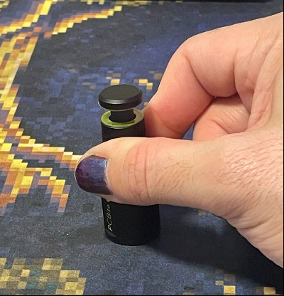
Ideally, you’ll want to place clips on the corners of the board to give yourself as much access to its parts as possible.
Legs/pins
The probe pins can be screwed onto the nonmagnetic ends of legs and, once you’re happy with their position, can be lightly applied to whichever test point on the board is of interest to you. Because the sharp pins on the probes are retractable and the ends of the legs are weighted, it’s possible to make a relatively solid connection to the board’s test points. You’ll have noticed the two other pins on each probe. Those are for connections to the wires of the Tigard, which we’ll go over next.
Tigard
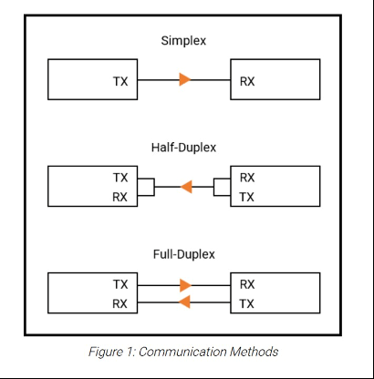
The Tigard is a multiprotocol, multivoltage hardware hacking tool. This orange board is what allows us to communicate over serial when connected to debug ports. The Tigard supports universal asynchronous receiver/transmitter (UART), JTAG, Serial Wire Debug (SWD), Inter- Integrated Circuit (i2c), and Serial Peripheral Interface (SPI) communication. In this lab, we’ll be focusing on UART communication, which is what the set of pins with the yellow headers on the Tigard are for.
The Tigard comes with multiple wires. For this lab, we’ll want to use the set of four with the red, black, green, and white wires. You’ll notice that at the end of each wire is a label. The red is labeled VTGT, for voltage; the black, GND, for ground; the green, TX, for transmit; and the white, RX, for receive. The ones of interest to us are ground, transmit, and receive. To power the Tigard, simply connect it to the laptop via the USB-C to USB-A cable.
Multimeter
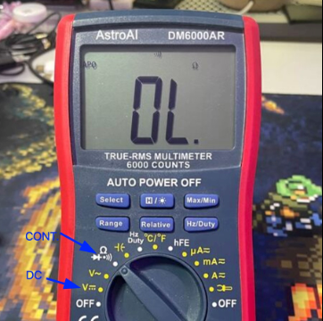
Some hackers prefer to use logic analyzers or even oscilloscopes to identify UART interfaces; however, that can be overkill. For our use case, we really need only a bit of knowledge about UART and our multimeter. There are many modes for multimeters with many use cases, but we’ll need to use only three: continuity mode, resistance mode, and direct current (DC) mode.
UART the only one for me
As mentioned above, UART stands for universal asynchronous receiver/transmitter. Basically, it’s a protocol that uses asynchronous serial communication from a transmitter to a receiver. Asynchronous here basically means that the one transmitting and the one receiving need to agree on the rate at which data will be exchanged before it’s exchanged.
Once a data rate (baud rate) is agreed upon, a message can be sent through a transmission channel (TX) to a receiving channel (RX).
That may seem abstract now, but what if the data being sent over serial could be converted to ASCII characters? What if you could send system commands to a device over serial? And what if that device were running, for example, a Linux operating system? You’d basically achieve what could be thought of as SSH over hardware. In other words, you’d have a shell!
So if finding UART means finding a shell, what exactly should you be looking for? Well, typically, UART is used for debugging during development. Debug interfaces on devices usually consist of one of the three P’s: pins, pads, or ports. UART interfaces usually consist of three or four pins/pads: ground (GND), receive (RX), and transmit (TX) and sometimes voltage (VCC). So basically, we’re going to poke around on any pins, pads, or ports that we think could be the UART interface (particularly ones in groups of three or four). Once we find a likely candidate, we’ll measure its voltage output.
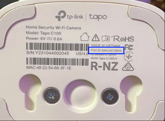
This is the time to take a good look at the board. Check out both sides. Make note of any pins, pads, or ports. Make note of any chips that may be of interest. Heck, if you’re curious about the camera’s schematics, look for the FCC ID of the camera and see if you can’t find it on https://fccid.io. (But you’ll have to use your own internet, as the laptops we’ve provided don’t have it.)
If you’ve taken your time analyzing the board, you may have a few thoughts about where the UART interface might be. You may be tempted to think the pins next to the power jack would be a good candidate.
It’s super common for devices to still have UART pins even after they’ve hit production (you’re very likely to see them in routers, for example). However, if you look at the black plastic bit that serves as the face of the camera, you’ll notice that its back has a little black block with six holes in it. And those six holes would align perfectly with the pins on the board, right? And then the PCB that the black block is attached to—what is its purpose? It turns out that the board is actually where the camera’s speaker and light are, which means that those six pins provide power for the light and signals for the speaker. So chances are we can rule out those pins altogether. On to the next candidate.
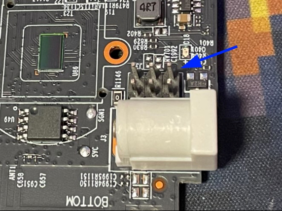
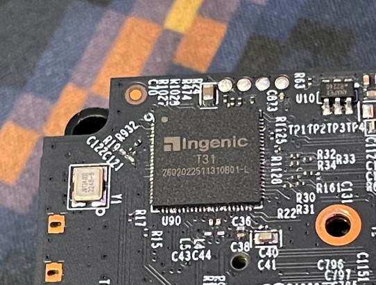
On the other side of the board, you’ll see the system on a chip (SoC), the T31 by Ingenic Semiconductor. This is the brains of the camera: the CPU, the memory, the video processor, and other peripherals. It even has a vector processor for deep learning operations (according to the camera’s marketing, it’s used for facial recognition). But that isn’t what’s interesting to us (even though it is a pretty cool chip).
Those four pads right next to the SoC look like a perfect candidate for a UART interface. Chances are during development, the pads had pins on them to make debugging easier. Now that the device is in production, however, those pins would have no utility. Keeping them on would just cost TP-Link extra money. Only one way to find out!
Multimeter time
It’s time to break out that multimeter. If this is your first time using a multimeter, don’t worry—we’ll be going over everything step by step, and if you have any questions, you can feel free to ask us! You’ll want to plug the black probe (negative) into the COM terminal and the red probe (positive) into the red terminal with the V and Ω symbol. (This is actually important, because if you plug your probes into the wrong terminal, you could damage the multimeter.) What we want to do is find out which of the pads is ground, receive (RX), transmit (TX), or voltage (VCC).
Let’s start with finding ground. Turn the dial to continuity mode, which is the setting with the sound wave symbol. This setting is going to tell us whether there’s low resistance in the circuit that the probes are creating. We’ll place the black probe on a grounded point and the red probe on each of the pads one by one. If you hear a beep, it’s because there’s low resistance between the pad and ground, which means that the pad is grounded.
Places to find ground include all board screws; a Wi‑Fi antenna ground; the ground pin of a DC barrel jack; and the SD card slot shield. With the power off, pick your ground and place your black probe on it. Then test the pads with the red probe. Once you’ve found your ground pad, make note of it.
Next we’ll move on to the other pads. While the device is still powered off, we can determine which of the pads is VCC by testing them against a known point of voltage. Let’s return to the pins of the DC jack, one of which is ground and one of which is VCC. You might think that the VCC pin of the barrel jack would be a good candidate, but there’s something weird about the C100: Its DC barrel jack takes 9 volts and then sends that through a voltage regulator to power the rest of the board at 3.3 volts. That means that a direct connection to the VCC pin of the barrel jack won’t return the measurements we’d need to determine whether a point in a 3.3-volt circuit is connected to VCC.
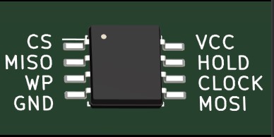
Luckily, there’s a flash chip (SOIC‑8) on the other side of the board.
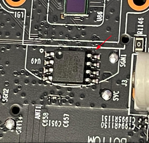
Why does that matter? SOIC8 chips like this one are typically used for flash memory, to store the device’s firmware. The chips often use a serial protocol, SPI, to communicate, and they usually have a little circle in their upper-left corner to indicate their correct orientation. But how does that help us?
Well, when an SOIC8 chip is configured to use the SPI interface, that circle is meant to point out the chip-select (CS) pin…which means that on the right is a VCC pin!
This kind of chip may not always be configured to use SPI. However, the configuration is common enough in embedded systems that it’s more likely than not to be the case. So with that in mind, let’s take some measurements!
Switch the dial of the multimeter to resistance mode (Ω). A good place to start is 20,000 ohms. We won’t worry too much about the meanings of the different numbered settings, as they’re not super relevant to the task at hand. Suffice it to say that the higher the number, the higher the resolution of our measurements.
When measuring resistance against VCC, you’ll want to first place the red probe on the known point of voltage and then use the black probe to test the pins. Remember: The lower the number, the lower the resistance. When measuring against VCC, that means that resistance of around 0– 1 ohms is sufficient to indicate that you’ve found a point connected to VCC. You’re going to have to remove the clips from the board to get that measurement. It’s going to be a little finicky, but it should be possible.
Once you’ve found your VCC, it’s time to look for the transmit pad. This is the channel through which the device will communicate with our receive channel. A good way to identify transmit is to look for fluctuations in voltage during boot time. That’s because when a device has boot logging enabled, which is often the case, the voltage fluctuates during boot as text is printed to the console. So you’ll want to turn the dial to DC mode, which is indicated by a V next to a dotted line beneath a straight line. A good setting in this case would be 20. Then put your black probe on ground and the red on your prospective transmit pad and power on the device. If you’re having trouble juggling your probes while powering on the device, you can try using the multimeter probes in the PCBite kit.
Once you’ve found your TX, you’ll also, by process of elimination, have found RX. But for posterity’s sake, here’s a good method for using a multimeter to identify receive: Follow the same process you used to find TX, but instead of looking for fluctuations in voltage, look for a silent unchanging reading that’s only slightly lower than the circuit’s voltage.
Getting a shell
Now that you’ve identified all your pads, it’s time to break out the Tigard! As a reminder, the pins with the yellow headers are for UART, and we’ll be using the set of four wires—one red, one black, one green, and one white labeled VTGT, GND, TX, and RX, respectively. If you look closely at the UART pins on the Tigard, you’ll see that each one is labeled with the corresponding wire. To start, mount the wires and plug in your Tigard. Then set up the PCBite legs and pins with the associated wires on the Tigard, and place the corresponding GND, TX, and RX pins on each of the UART pads.
Note the little switch next to the USB-C port on the Tigard. That switch is how you’ll specify the voltage that the Tigard will run at. You’ll want to make sure that it matches the voltage of the board; otherwise, you won’t be able to communicate with the board and could potentially even damage it.
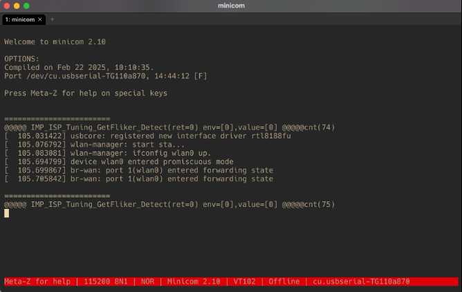
We’re almost ready to go! The last step before we can actually talk to the board is running the software that will allow us to interface with the camera via serial over USB. There are several options for this, such as screen, PuTTY, and picocom—and some terminals even have built-in serial support. The tool we’ll be using for this demonstration, though, is minicom.
Open your terminal and run minicom --help to see which flags are accepted. The ones we’re
interested in are the device flag (-D) and the baud rate flag (-b), both of which are pretty
straightforward. If you’ve plugged the Tigard into your laptop’s USB port and are running Linux
or macOS, it will create a device that you can access via the /dev directory. On a Windows
machine, the device would appear as one of the COM ports, which can be viewed in the Device
Manager.
Since you’re on Linux, you’ll be looking for a device that begins with /dev/tty. Specifically, the
Tigard will be either /dev/ttyACM0 or /dev/ttyUSB0. You can confirm which is available to you
by running ls /dev/tty* in the terminal and looking for either of the two in the output. Once
you’ve confirmed your device, you can run the command minicom -D /dev/ttyACM0 (or
/dev/ttyUSB0).
Recall that our two communicating devices need to agree on a rate of data transfer in order to talk to each other. Well, that’s what the baud rate is. At the moment, we don’t know what the baud rate of the UART is, but there are ways we could manually figure it out. However, to save some time, we could also just guess! There are a lot of different baud rates, but a handful of them are used the most frequently.
- 110
- 150
- 300
- 1200
- 2400
- 4800
- 9600
- 19200
- 38400
- 57600
- 115200
- 230400
- 460800
- 921600
That does narrow things down significantly, but we can narrow things down even further. In my experience, the most common baud rate for UART is 115200. That is always my default guess, and only a handful of times has it been incorrect.
So finally, your minicom command should look like this:
sh minicom -D /dev/ttyACM0 -b 115200
WE’RE IN 😎💻
 There’s only one problem.
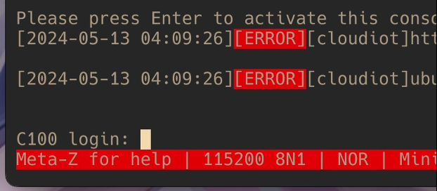
We only havea login prompt. No shell. What can we do?
Think like a hacker
One of the most valuable things a hacker has is that little voice in their head that refuses to take “no” for an answer—the voice that responds with “Oh yeah? We’ll see.” Right now, that login prompt is telling us “no.” Even the C100 and TP-Link don’t want us to get a root shell. So let’s see if we can.
One of my favorite ways to root a smart device is to mess with its bootloader. It’s the first program run on such a device and is responsible for setting up the device’s clock, memory, and peripherals and loading the kernel into executable memory. There are many different kinds of bootloaders, but there’s one in particular that I enjoy messing with: U-Boot. If we can find a way to drop in to U-Boot’s shell during startup, chances are we’ll be able to do everything from dumping the firmware to flashing our own firmware. We may even be able to mount the filesystem in memory, which would give us our root shell.
We can check whether the C100 is running U-Boot by enabling minicom’s logging functionality. On Linux, you can do that by pressing ctrl+a and then pressing l. You’ll then be prompted to name the log file and specify where minicom should write it. After that, just reboot the camera and capture all of its boot logs.
Once you’ve finished capturing the logs, you can start checking them out. Somewhere around the top of the log file, you should see something like this:
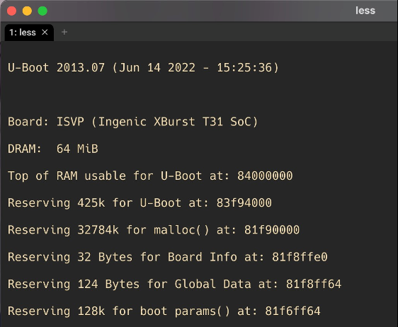
All right, we’ve got U-Boot! That gives us a pretty solid lead.
There are some stipulations, of course. For instance, we’ll run into problems if the vendor (TPLink) has modified U-Boot in a way that removes all of its cool functionality, and there has to be a way to halt the boot process and drop in to the U-Boot shell. Sometimes it’s possible to halt the boot process by pressing enter at the right time, before the kernel has been loaded. Give it a try—it’s worked on certain versions of the C100 firmware.
It’s also fairly common for TP-Link to use password-protected bootloaders on its devices. In that case, instead of just repeatedly smashing enter during boot, you would type in the password, hit enter, and then be dropped in to the U-Boot shell. Luckily for us, previous research on other Tapo devices has shown that TP-Link tends to reuse its bootloader passwords on many devices, with tpl and slp being the most common. So go ahead and give those a try.
If it becomes annoying to unplug the camera and plug it back in to restart the boot, hopefully, we’ve provided you with a surge protector that you can use to switch it on and off more easily.
Another strategy that I often use is connecting the DC jack pins on the back of the device to my multimeter probe for a split second to short the power and restart the boot, as shown below.
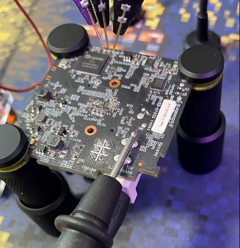
Just a quick tap should be fine and won’t hurt anything.
Unfortunately, neither of those tactics work on the firmware version used on the camera.
So does that mean we’re out of options? Of course not!
It turns out that the C100 actually has two bootloaders. The primary bootloader is stored in ROM or protected flash and is responsible for low-level system initialization, and the secondary bootloader resides in flash memory and handles firmware updates, security validation, and loading of the filesystem. What we want to do is interrupt the secondary bootloader so that we can drop in to the U-Boot shell. But how can we do that?
Remember our little buddy the SOIC8 chip? That’s our flash memory chip, right? What if we were to mess with it during the boot process? It turns out that by grounding the CS pin, we can render the secondary bootloader unable to find the kernel at the memory location it was given. In that case, U-Boot will try to find the kernel about four more times before it just peters out and drops us in to our U-Boot shell!

You can use one of your multimeter probes to ground the CS pin just at the time that you start seeing the probe spend 4 ms messages. To ground the pin, just lightly bridge the CS pin to the pin next to it and then hold it until you see the shell prompt. This will definitely be a bit finicky. Personally, I’ve found it easier to use a SIM card pin to ground the CS pin. Eventually, though, you’ll get it.
Now that you’re in the U-Boot shell, what can you do? Quite a bit, actually. If you run the help
command, you’ll see that TP-Link has left us quite a bit of functionality to work with. Particularly
interesting commands include the md, mm, and mw commands, which allow us to mess with
memory addresses. Honestly, we could probably use them to just dump the firmware, but I’ll
leave figuring that out to the curious. What we’re here for is root!
If you run the printenv command, you’ll see all the environment variables that U-Boot reads to
finish the boot process. You may need to shrink your terminal’s text to fit everything, which you
can do by pressing ctrl+-. Alternatively, you can enable line wrapping in minicom by pressing
ctrl+a and w.
So what are we looking for here? How do we parse this information? Well, if you’re familiar with
Linux or macOS, you may have experience with configuring your terminal’s shell. You can think
of these variables like the aliases you might put in your .bashrc file. But which of these “aliases”
is of interest to us? Well, do you see the init variable in the bootargs commands? Its value,
/etc/preinit, is pointing to a file on the Linux filesystem. That means that preinit is likely a
script that is run after the secondary bootloader has completed its boot process and the filesystem
has been mounted.
Now, what if we could change this value and make it point to a binary instead of to
/etc/preinit? If you read the output of the help command, you might have noticed that
technically, we could do that through the setenv command. And what if we were to point it to
/bin/bash, for example? Well, since the C100 doesn’t have the bash binary, it wouldn’t do very
much. But maybe there’s another shell that we could use—one that comes installed on practically
every Linux installation? Indeed, the /bin/sh binary is the most likely candidate for an
alternative. So let’s try setting init to /bin/sh!
setenv bootargs console=ttyS1,115200n8 mem=45M@0x0 rmem=19M@0x2d00000
                                    root=/dev/mtdblock6 rootfstype=squashfs spdev=/dev/mtdblock7 noinitrd
                                    init=/bin/sh
Then, to run our new boot command, we’ll just run boot and...
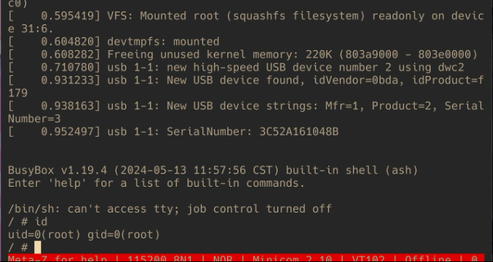
We’re root! 😱🎉
From this point on, we can do whatever we want with the system, whether that’s dumping the firmware, putting our own backdoored firmware on the camera, or extracting the filesystem and reverse-engineering the libraries and binaries to find vulnerabilities. Heck, if you want to see something really cool, run this command:
/etc/preinit && cat /tmp/etc/uc_conf/user_managementThis will mount the filesystem and then display the content of a config file containing credentials used to authenticate to the camera’s video stream over HTTP! Our team has yet to confirm whether those credentials are generated dynamically on first boot or are simply hard-coded and changed during firmware upgrades. But either way, the exposure of that information could have real implications for people’s privacy. No bueno, to say the least.
What can be done for the C100?
Because the flash chip is a hardware component, there’s not much that can be done to modify it. But maybe it would be possible to modify the bootloader such that it more gracefully handles the inability to find kernel images? Maybe it’d be a good idea to not hard-code the credentials for sensitive services like video streams? Removing U-Boot’s ability to read/write memory and set environment variables from its shell wouldn’t hurt either. The point is that there are many potential improvements that could be made here.
Unfortunately, the solution to this issue is unclear, since few of the mitigation options we’ve just run through could be applied to devices already in people’s homes. What we do know is this: The vulnerability still exists on more recent firmware versions, though TP-Link has modified the firmware such that the operating system will reboot after a few minutes if a root shell has been entered. However, that change in itself doesn’t prevent the extraction of video stream credentials or the dumping of the firmware, for that matter.
Indeed, there are many more improvements to be made to the C100 and the Tapo line in general, if the wealth of security research being done on that tech is any indication. Regardless, we hope you enjoyed hacking with us!